5.
Process Improvement
5.5.
Advanced topics
5.5.6.
|
What are Taguchi designs?
|
|
|
Taguchi designs are related to fractional factorial designs - many
of which are large screening designs
|
Genichi Taguchi, a Japanese engineer, proposed several approaches to
experimental designs that are sometimes called "Taguchi Methods." These
methods utilize two-, three-, and mixed-level fractional factorial
designs. Large screening designs seem to be particularly favored by
Taguchi adherents.
Taguchi refers to experimental design as "off-line quality control"
because it is a method of ensuring good performance in the design stage
of products or processes. Some experimental designs, however, such as
when used in evolutionary operation, can be used on-line while the
process is running. He has also published a booklet of design
nomograms ("Orthogonal
Arrays and Linear Graphs," 1987, American Supplier Institute) which
may be used as a design guide, similar to the table of fractional
factorial designs given
previously in Section 5.3.
Some of the well-known Taguchi orthogonal arrays (L9, L18, L27 and L36)
were given earlier when three-level,
mixed-level and fractional factorial designs were discussed.
If these were the only aspects of "Taguchi Designs," there would be
little additional reason to consider them over and above our previous
discussion on factorials. "Taguchi" designs are similar to our familiar
fractional factorial designs. However, Taguchi has introduced several
noteworthy new ways of conceptualizing an experiment that are very
valuable, especially in product development and industrial engineering,
and we will look at two of his main ideas, namely Parameter Design and
Tolerance Design.
|
|
|
Parameter Design
|
|
Taguchi advocated using inner and outer array designs to take into
account noise factors (outer) and design factors (inner)
|
The aim here is to make a product or process less variable (more robust)
in the face of variation over which we have little or no control. A
simple fictitious example might be that of the starter motor of an
automobile that has to perform reliably in the face of variation in
ambient temperature and varying states of battery weakness. The
engineer has control over, say, number of armature turns, gauge of
armature wire, and ferric content of magnet alloy.
Conventionally, one can view this as an experiment in five factors.
Taguchi has pointed out the usefulness of viewing it as a set-up of
three inner array factors (turns, gauge, ferric %) over which we have
design control, plus an outer array of factors over which we have
control only in the laboratory (temperature, battery voltage).
|
|
Pictorial representation of Taguchi designs
|
Pictorially, we can view this design as being a conventional
design in the inner array factors (compare
Figure 3.1) with the addition
of a "small" outer array factorial design at each corner of the
"inner array" box.
Let I1 = "turns," I2 = "gauge," I3 = "ferric %," E1 = "temperature,"
and E2 = "voltage." Then we construct a 23 design "box" for
the I's, and at each of the eight corners so constructed, we place a
22 design "box" for the E's, as is shown in Figure 5.17.
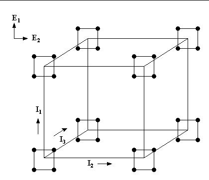
FIGURE 5.17: Inner 23 and outer 22 arrays
for robust design
with `I' the inner array, `E' the outer array.
|
|
An example of an inner and outer array designed experiment
|
We now have a total of 8x4 = 32 experimental settings, or runs. These
are set out in Table 5.7, in which the 23 design in the I's
is given in standard order on the left of the table and the
22 design in the E's is written out sideways along the top.
Note that the experiment would not be run in the standard order but
should, as always, have its runs randomized. The output measured is
the percent of (theoretical) maximum torque.
|
|
Table showing the Taguchi design and the responses from the experiment
|
TABLE 5.7: Design table, in standard order(s) for the
parameter design of Figure 5.9
|
Run
Number
|
|
1
|
2
|
3
|
4
|
|
|
|
|
|
|
I1
|
I2
|
I3
|
E1
E2
|
-1
-1
|
+1
-1
|
-1
+1
|
+1
+1
|
Output
MEAN
|
Output
STD. DEV
|
|
|
|
|
|
1
|
-1
|
-1
|
-1
|
|
75
|
86
|
67
|
98
|
81.5
|
13.5
|
|
2
|
+1
|
-1
|
-1
|
|
87
|
78
|
56
|
91
|
78.0
|
15.6
|
|
3
|
-1
|
+1
|
-1
|
|
77
|
89
|
78
|
8
|
63.0
|
37.1
|
|
4
|
+1
|
+1
|
-1
|
|
95
|
65
|
77
|
95
|
83.0
|
14.7
|
|
5
|
-1
|
-1
|
+1
|
|
78
|
78
|
59
|
94
|
77.3
|
14.3
|
|
6
|
+1
|
-1
|
+1
|
|
56
|
79
|
67
|
94
|
74.0
|
16.3
|
|
7
|
-1
|
+1
|
+1
|
|
79
|
80
|
66
|
85
|
77.5
|
8.1
|
|
8
|
+1
|
+1
|
+1
|
|
71
|
80
|
73
|
95
|
79.8
|
10.9
|
|
(The reader can download the data as a
text file.)
|
|
Interpretation of the table
|
Note that there are four outputs measured on each row. These correspond
to the four `outer array' design points at each corner of the `outer
array' box. As there are eight corners of the outer array box, there
are eight rows in all.
Each row yields a mean and standard deviation % of maximum torque.
Ideally there would be one row that had both the highest average torque
and the lowest standard deviation (variability). Row 4 has the highest
torque and row 7 has the lowest variability, so we are forced to
compromise. We can't simply 'pick the winner.'
|
|
Use contour plots to see inside the box
|
One might also observe that all the outcomes occur at the corners
of the design 'box', which means that we cannot see 'inside' the box.
An optimum point might occur within the box, and we can search for
such a point using contour plots. Contour plots were illustrated in
the example of response surface
design analysis given in Section 4.
|
|
Fractional factorials
|
Note that we could have used fractional factorials for either the
inner or outer array designs, or for both.
|
|
|
Tolerance Design
|
|
Taguchi also advocated tolerance studies to determine, based on a
loss or cost function, which variables have critical tolerances that
need to be tightened
|
This section deals with the problem of how, and when, to specify
tightened tolerances for a product or a process so that quality and
performance/productivity are enhanced. Every product or process has a
number, perhaps a large number, of components. We explain here how
to identify the critical components to target when tolerances have to
be tightened.
It is a natural impulse to believe that the quality and performance
of any item can easily be improved by merely tightening up on some or
all of its tolerance requirements. By this we mean that if the old
version of the item specified, say, machining to ± 1 micron, we
naturally believe that we can obtain better performance by specifying
machining to ± ½ micron.
This can become expensive, however, and is often not a guarantee of
much better performance. One has merely to witness the high initial
and maintenance costs of such tight-tolerance-level items as space
vehicles, expensive automobiles, etc. to realize that tolerance
design, the selection of critical tolerances and the re-specification
of those critical tolerances, is not a task to be undertaken without
careful thought. In fact, it is recommended that only after
extensive parameter design studies have been completed should
tolerance design be performed as a last resort to improve
quality and productivity.
|
|
|
Example
|
|
Example: measurement of electronic component made up of two components
|
Customers for an electronic component complained to their supplier that
the measurement reported by the supplier on the as-delivered items
appeared to be imprecise. The supplier undertook to investigate the
matter.
The supplier's engineers reported that the measurement in question was
made up of two components, which we label x and y, and
the final measurement M was reported according to the standard
formula
M = K x/y
with 'K' a known physical constant. Components x and
y were measured separately in the laboratory using two different
techniques, and the results combined by software to produce M.
Buying new measurement devices for both components would be
prohibitively expensive, and it was not even known by how much the
x or y component tolerances should be improved to produce
the desired improvement in the precision of M.
|
|
Taylor series expansion
|
Assume that in a measurement of a standard item the 'true' value of
x is xo and for y it is
yo. Let f(x, y) = M; then the
Taylor Series expansion for f(x, y) is
\( \begin{array}{lcl}
f(x,y) & = & f(x_{o},y_{o}) + (x - x_{o})\frac{df}{dx} + \\
& & (y - y_{o})\frac{df}{dy} +
(x - x_{o})^{2}\frac{d^{2}f}{dx^{2}} \\
& & + (y - y_{o})^{2}\frac{d^{2}y}{dy^{2}} +
(x - x_{o})(y - y_{o})\frac{d^{2}f}{dxdy} + \\
& & \mbox{(higher-order terms)}
\end{array}
\)
with all the partial derivatives, 'df/dx', etc.,
evaluated at (xo, yo).
|
|
Apply formula to M
|
Applying this formula to M(x, y) =
Kx/y, we obtain
\( \begin{array}{lcl}
M(x,y) & = & K\frac{x_o}{y_o} + (x - x_{o})\frac{K}{y_{o}} -
(y - y_{o})\frac{Kx_{o}}{y_{o}^{2}} - \\
& & 2(y - y_{o})^{2}\frac{K}{y_{o}^{3}} -
(x - x_{o})(y - y_{o})\frac{K}{y_{o}^{2}} \\
& & + \mbox{(higher-order terms)}
\end{array}
\)
It is assumed known from experience that the measurements of x
show a distribution with an average value xo, and
with a standard deviation
σx = 0.003 x-units.
|
|
Assume distribution of x is normal
|
In addition, we assume that the distribution of x is normal.
Since 99.74% of a normal distribution's range is covered by
6σ, we take 3σ = 0.009
x-units to be the existing tolerance Tx for
measurements on x. That is, Tx = ±
0.009 x-units is the 'play' around xo that
we expect from the existing measurement system.
|
|
Assume distribution of y is normal
|
It is also assumed known that the y measurements show a normal
distribution around yo, with standard deviation
σy = 0.004 y-units. Thus
Ty = ± 3σy =
±0.012.
|
|
Worst case values
|
Now ±Tx and ±Ty may
be thought of as 'worst case' values for (x-xo)
and (y-yo). Substituting Tx
for (x-xo) and Ty for
(y-yo) in the expanded formula for
M(x, y), we have
\( \begin{array}{lcl}
M_{T} & = & K\frac{x_o}{y_o} +
T_{x}\frac{K}{y_{o}} - T_{y}\frac{Kx_{o}}{y_{o}^{2}} -
2 T_{y}^{2}\frac{K}{y_{o}^{3}} -
T_{x}T_{y}\frac{K}{y_{o}^{2}} \\
& & + \mbox{(higher-order terms)}
\end{array}
\)
|
|
Drop some terms
|
The \( T_{y}^{2} \)
and TxTy terms, and all terms of higher
order, are going to be at least an order of magnitude smaller than
terms in Tx and in Ty, and for this
reason we drop them, so that
\( M_{T} = K\frac{x_o}{y_o} + T_{x}\frac{K}{y_{o}} -
T_{y}\frac{Kx_{o}}{y_{o}^{2}} \)
|
|
Worst case Euclidean distance
|
Thus, a 'worst case' Euclidean distance
\( \delta \)
of M(x, y) from its ideal value
\( K \frac{x_{o}}{y_{o}} \)
is (approximately)
\( \begin{array}{lcl}
\Delta & = & \sqrt{\left( T_{x}\frac{K}{y_{o}} \right) ^2 +
\left( T_{y}\frac{Kx_{o}}{y_{o}^{2}} \right) ^2} \\
& = & \sqrt{\left( 0.009 \frac{K}{y_{o}} \right) ^{2} +
\left( 0.012 \frac{Kx_{o}}{y_{o}^{2}} \right) ^{2} }
\end{array}
\)
This shows the relative contributions of the components to the
variation in the measurement.
|
|
Economic decision
|
As yo is a known quantity and reduction in
Tx and in Ty each carries its own
price tag, it becomes an economic decision whether one should spend
resources to reduce Tx or Ty, or
both.
|
|
Simulation an alternative to Taylor series approximation
|
In this example, we have used a Taylor series approximation to obtain
a simple expression that highlights the benefit of Tx
and Ty. Alternatively, one might simulate values of
M = K*x/y, given a specified
(Tx,Ty) and
(x0,y0), and then summarize the
results with a model for the variability of M as a function of
(Tx,Ty).
|
|
Functional form may not be available
|
In other applications, no functional form is available and one must use
experimentation to empirically determine the optimal tolerance design.
See Bisgaard
and Steinberg (1997).
|

