
|
|
DRAWName:
By default, the coordinates are in (0,100) screen units. You can also specify that the coordinates are in units of the most recent plot (referred to as data units). Screen or data units can be specified independently for the x and y coordinates. The arguments can be parameters (or numbers), variables, or a mix of parameters and variables. Any arguments that are variables must be the same length. If variable arguments are used, a line will be drawn for each row of the variables (arguments given as parameters will use the same value for all lines drawn). Coordinates can specify either absolute units or relative units. For example,
will draw a line from (10,10) to (50,50) while
will draw a line from (10,10) to (10+50,10+50), that is from (10,10) to (60,60). The DRAW command is most typically used to annotate a previously generated plot. For example, it may be used to draw reference lines.
where <x1> is a number, parameter or variable that specifies the x coordinate for one end of the line segment; <y1> is a number, parameter or variable that specifies the y coordinate for one end of the line segment; <x2> is a number, parameter or variable that specifies the x coordinate for the other end of the line segment; and <y2> is a number, parameter or variable that specifies the y coordinate for the other end of the line segment. If all arguments are parameters, this syntax draws from (x1,y1) to (x2,y2) using screen coordinates. If the arguments are variables, one line will be drawn for each row of the variables. The arguments can be a mix of parameters and variables. However, all variables must be of the same length and any parameter arguments will use the same value for all lines drawn. Since this syntax uses screen units, all values should be in the 0 to 100 range. The keyword RELATIVE is optional. If omitted, the coordinates are in absolute units. If RELATIVE is included, the (<x2>,<y2>) coordinates are relative to (<x1>,<y1>).
where <x1> is a number, parameter or variable that specifies the x coordinate for one end of the line segment; <y1> is a number, parameter or variable that specifies the y coordinate for one end of the line segment; <x2> is a number, parameter or variable that specifies the x coordinate for the other end of the line segment; and <y2> is a number, parameter or variable that specifies the y coordinate for the other end of the line segment. This syntax is similar to Syntax 1. However, the coordinates are in data units rather than screen units. The keyword RELATIVE is optional. If omitted, the coordinates are in absolute units. If RELATIVE is included, the
where <x1> is a number, parameter or variable that specifies the x coordinate for one end of the line segment; <y1> is a number, parameter or variable that specifies the y coordinate for one end of the line segment; <x2> is a number, parameter or variable that specifies the x coordinate for the other end of the line segment; and <y2> is a number, parameter or variable that specifies the y coordinate for the other end of the line segment. The "xxxx" string consists of exactly four characters where each character is either "S" to deonote screen units or "D" to denote data units. The first character specifies the units for <x1>, the second character specifies the units for <y1>, the third character specifies the units for <x2>, and the fourth character specifies the units for <y2>. This syntax is similar to Syntax 1. However, the coordinates can be drawn in a mix of screen and data units. The keyword RELATIVE is optional. If omitted, the coordinates are in absolute units. If RELATIVE is included, the
where <x1> is a number or parameter in the decimal range 0 to 100 that specifies the x coordinate for one end of the line segment; and <y1> is a number or parameter in the decimal range 0 to 100 that specifies the y coordinate for one end of the line segment. This syntax draws from the current position (typically specified by a MOVE command) to (x1,y1).
The keyword RELATIVE is optional. If omitted, the coordinates are in
absolute units. If RELATIVE is included, the (<x1>,
where <x1> is a number or parameter in the decimal range 0 to 100 that specifies the x coordinate for the first point of the line segment; <y1> is a number or parameter in the decimal range 0 to 100 that specifies the y coordinate for the first point of the line segment; <x2> is a number or parameter in the decimal range 0 to 100 that specifies the x coordinate for the second point of the line segment; <y2> is a number or parameter in the decimal range 0 to 100 that specifies the y coordinate for the second point of the line segment; <xn> is a number or parameter in the decimal range 0 to 100 that specifies the x coordinate for the nth point of the line segment; <yn> is a number or parameter in the decimal range 0 to 100 that specifies the y coordinate for the nth point of the line segment. This syntax draws from (x1,y1) to (x2,y2) to (x3,y3) and so on for each coordinate pair listed. The coordinates are given in screen units. The keyword RELATIVE is optional. If omitted, the coordinates are in absolute units. If RELATIVE is included, the current point is relative to the previous point (the initial point (<x1> and <y1>) is interpreted as absolute units).
where <x1> is a number or parameter in the decimal range 0 to 100 that specifies the x coordinate for the first point of the line segment; <y1> is a number or parameter in the decimal range 0 to 100 that specifies the y coordinate for the first point of the line segment; <x2> is a number or parameter in the decimal range 0 to 100 that specifies the x coordinate for the second point of the line segment; <y2> is a number or parameter in the decimal range 0 to 100 that specifies the y coordinate for the second point of the line segment; <xn> is a number or parameter in the decimal range 0 to 100 that specifies the x coordinate for the nth point of the line segment; <yn> is a number or parameter in the decimal range 0 to 100 that specifies the y coordinate for the nth point of the line segment. This syntax draws from (x1,y1) to (x2,y2) to (x3,y3) and so on for each coordinate pair listed. The coordinates are given in data units. The keyword RELATIVE is optional. If omitted, the coordinates are in absolute units. If RELATIVE is included, the current point is relative to the previous point (the initial point (<x1> and <y1>) is interpreted as absolute units).
DRAW 50 20 50 90 DRAWDATA 1 100 1 200 DRAWDSDS 1 20 1 90 DRAWDSDS X1 20 X1 90
1994/04: Support for data units 2018/04: Support for variable arguments
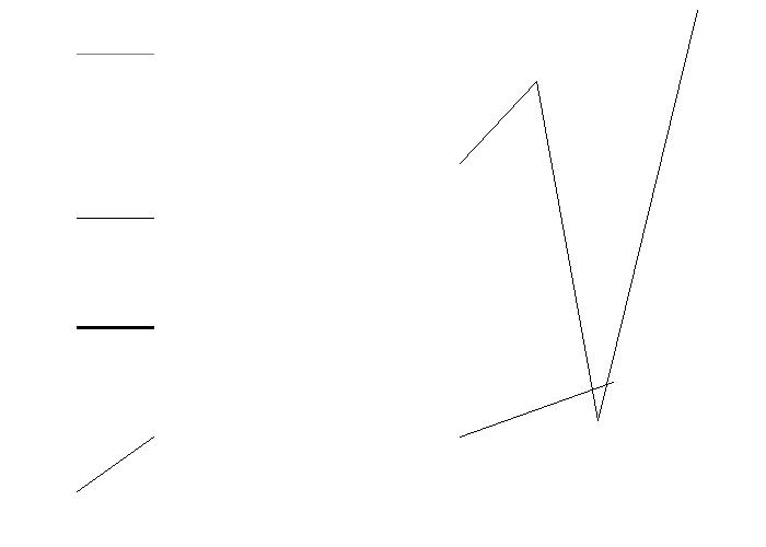
DRAW 10 10 20 20
DRAW 60 20 80 30
.
THICKNESS 0.7
DRAW 10 40 20 40
THICKNESS 0.3
.
LINE DASH
DRAW 10 60 20 60
LINE SOLID
.
LINE COLOR G50
DRAW 10 90 20 90
LINE COLOR BLACK
.
THICKNESS 0.2
DRAW 60 70 70 85 78 23 91 98
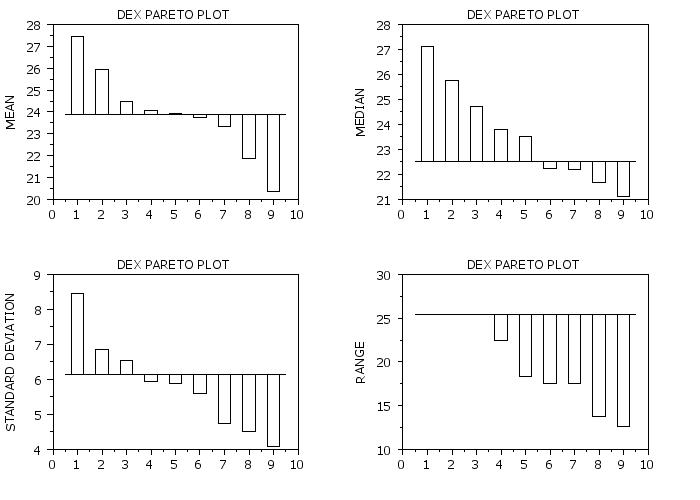
 Program 2:
SKIP 25
READ SHEESLE2.DAT Y PROC PLANT SPEED SHIFT PROC
.
BAR ON
BAR WIDTH 0.5
LINES BLANK BLANK
TITLE DEX PARETO PLOT
TITLE OFFSET 2
.
MULTIPLOT 2 2
MULTIPLOT CORNER COORDINATES 0 0 100 100
MULTIPLOT SCALE FACTOR 2
Y1LABEL MEAN
LET A = MEAN Y
BAR BASE A
DEX MEAN PARETO PLOT Y PROC PLANT SPEED SHIFT
LET NPTS = SIZE XPLOT
LET XFIRST = 0.5
LET XLAST = (NPTS-2) + 0.5
LINE SOLID
DRAWDATA  XFIRST A XLAST A
LINE BLANK
.
Y1LABEL MEDIAN
LET A = MEDIAN Y
BAR BASE A
DEX MEDIAN PARETO PLOT Y PROC PLANT SPEED SHIFT
LINE SOLID
DRAWDATA  XFIRST A XLAST A
LINE BLANK
.
YLIMITS
Y1LABEL STANDARD DEVIATION
LET A = STANDARD DEVIATION Y
BAR BASE A
DEX SD PARETO PLOT Y PROC PLANT SPEED SHIFT
LINE SOLID
DRAWDATA  XFIRST A XLAST A
LINE BLANK
.
Y1LABEL RANGE
LET A = RANGE Y
BAR BASE A
DEX RANGE PARETO PLOT Y PROC PLANT SPEED SHIFT
LINE SOLID
DRAWDATA  XFIRST A XLAST A
LINE BLANK
END OF MULTIPLOT
|
Privacy
Policy/Security Notice
NIST is an agency of the U.S.
Commerce Department.
Date created: 04/19/2018 | ||||||||||||||||||||||||||||||||||||||||||||||||||||