|
|
CONDITION PLOTName:
conditional on the value of a third variable. Although condition plots can be generated using the MULTIPLOT and SUBSET commands (and typically LOOPING), the CONDITION PLOT command allows some fairly involved multiplots to be generated with a minimum number of commands (and without looping).
is equivalent to
PLOT Y X TAG SUBSET TAG = 1 PLOT Y X TAG SUBSET TAG = 2 PLOT Y X TAG SUBSET TAG = 3 END OF MULTIPLOT
You can use the "CODE" commands:
LET TAG = CODE4 Y LET TAG = CODE8 Y LET TAG = CODE
CODE2 codes TAG as 1 or 2 depending on whether the corresponding
points in Y fall below or above the median. CODE4 divides
the data into quartiles (and code TAG as 1, 2, 3, 4 according
to which quartile the data falls into). Similarly, CODE8
divides Y into octiles. CODE
For maximum control, you can do something like the following:
This concept generalizes to other types of plots other than
scatter plots. Dataplot supports the CONDITION PLOT for a
number of univariate and bivariate plots.
There are a number of alternatives for the appearance of this
plot. Dataplot tries to balance simplicity with flexibility
by using default settings, but providing numerous SET commands
to control the appearance of the plot. These are described in
detail in the NOTES section below.
The CONDITION PLOT is similar to the factor plot. A simple
explanation of the difference is that the factor plot
does something like
while the condition plot does something like
where <Y> is the response (y axis) variable; <X> is the factor (x axis) variable; <TAG> is the conditioning variable; and where the <SUBSET/EXCEPT/FOR qualification&gr; is optional. This syntax is used when generating a bivariate plot.
where <Y1> ... <Yk> are the response (y axis) variables; <X> is the factor (x axis) variable; <TAG> is the conditioning variable; and where the <SUBSET/EXCEPT/FOR qualification> is optional. This syntax is used when generating a bivariate plot with multiple response variables. That is, we are effectively doing
CONDITION PLOT Y2 X TAG etc. where each response variable is plotted as a single row of plots.
where <Y> is the response (y axis) variable; <X> is the factor (x axis) variable; <TAG1> is the first conditioning variable; <TAG2> is the second conditioning variable; and where the <SUBSET/EXCEPT/FOR qualification&gr; is optional. This syntax is used when generating a bivariate plot with two conditioning variables. The rows of the plot matrix correspond to the distinct values of the first tag variable while the columns correspond to the distinct values of the second tag variable. The most general case, multiple response variables with two conditioning variables, is still being tested.
where <Y> is the response (y axis) variable; <TAG> is the conditioning variable; and where the <SUBSET/EXCEPT/FOR qualification&gr; is optional. This syntax is used when generating a univariate plot.
where <Y1> ... <Yk> are the response (y axis) variables; <TAG> is the conditioning variable; and where the <SUBSET/EXCEPT/FOR qualification> is optional. This syntax is used when generating a univariate plot with multiple response variables. That is, we are effectively doing
CONDITION PLOT Y2 TAG &etc. where each response variable is plotted as a single row of plots.
where <Y> is the response (y axis) variable; <TAG1> is the first conditioning variable; <TAG2> is the second conditioning variable; and where the <SUBSET/EXCEPT/FOR qualification&gr; is optional. This syntax is used when generating a univariate plot with two conditioning variables. The rows of the plot matrix correspond to the distinct values of the first tag variable while the columns correspond to the distinct values of the second tag variable. The most general case, multiple response variables with two conditioning variables, is still being tested.
CONDITION PLOT Y TAG
SET CONDITION PLOT TYPE PLOT
SET CONDITION PLOT TYPE PLOT
where
The folllowing plot two variables (e.g., BIHISTOGRAM Y1 Y2).
Use either syntax 2 or syntax 3 above, depending on whether
you have one or multiple response variables, for the
CONDITION PLOT command.
The folllowing plot one variables (e.g., HISTOGRAM Y1).
Use syntax 1 above.
The plot TITLE identifies the value of the conditioning
variable for all of the above plot types.
Where it makes sense, Dataplot will generate a dummy plot
of the full data set first in order to generate common x and y
axis scales. For some plots, this does not make sense. For
example, a full sample PPCC plot does not necessarily encompass
the range of the PPCC plots generated from subsets of the data.
Dataplot automatically defines X1LABEL, X2LABEL, and YLABEL
commands for these plots. You can control the attributes
of these labels with the standard label setting commands.
If you have defined variable labels (with the VARIABLE LABEL
command), these will automatically be substituted for variable
names in the labels.
If you have defined variable labels with the VARIABLE LABEL
command and you want to suppress the automatic expansion
of the variable name to the variable label, enter
To restore the default that variable names will be expanded to
the corresponding variable label, enter
SET CONDITION PLOT CONDITION VARIABLES <value2> where <value1> identifies the number of response variables and <value2> identifies the number of conditioning variables. On the CONDITION PLOT command, Dataplot assummes that the response variables (y axis) come first, then the factor variable (x axis) if needed, and then the conditioning variables. The default is one response variable and one conditioning variable.
OFF means that all axis labels are suppressed (this can be useful if a large number of variables are being plotted). ON means that both X and Y axis labels are printed. XON only plots the x axis labels and YON only plots the y axis labels. BOX is a special option that creates an extra column on the left and an extra row on the bottom. The axis label is printed in this box. BOX is typically reserved for the case where there is a natural division of rows and columns (i.e., either multiple response variables or two conditioning variables). The default is ON (both x and y axis labels are printed).
BOTTOM specifies that the x axis labels are printed on the bottom axis (on the last row only). TOP specifies that the x axis labels are printed on the top axis (first row only). ALTERNATE specifies that the x axis labels alternate between the top (first row) and bottom axis (last row). We recommend using the TIC OFFSET command to avoid overlap of axis labels and tic marks. The default is ALTERNATE.
LEFT specifies that the y axis labels are printed on the left axis (on the first column only). RIGHT specifies that the y axis labels are printed on the right axis (last column only). ALTERNATE specifies that the y axis labels alternate between the left (first column) and right axis (last column). We recommend using the TIC OFFSET command to avoid overlap of axis labels and tic marks. The default is ALTERNATE.
DEFAULT connects neighboring frames (i.e., the FRAME CORNER
COORDINATES are set to 0 0 100 100). USER uses whatever
frame coordinates are currently set (15 20 85 90 by default)
and makes no special provisions for axis labels and tic marks
(i.e., you set them as you normally would, each plot uses
whatever you have set). CONNECTED uses whatever frame
coordinates have been set by the user, but it draws the axis
labels and tic marks as if DEFAULT were being used (that is, as
determined by the SET CONDITION PLOT
The default is DEFAULT.
NORMAL means that all tic labels are plotted at a distance determined by the TIC LABEL DISPLACEMENT command. STAGGERED means that alternating plots will be staggered. That is, one will use the standard displacement while the next uses a staggered value. Entering this command with a numeric value specifies the amount of the displacement for the staggered tic labels. For example,
SET CONDITION PLOT LABEL DISPLACEMENT STAGGERED SET CONDITION PLOT LABEL DISPLACEMENT 25 These commands specify that the default tic label displacement is 10 and the staggered tic mark label displacement is 25.
NONE means that no fitted line is plotted. LOWESS means that a locally weighted least squares line will be overlaid. LINE means that a linear fit (Y = A0 + A1*X) will be overlaid. QUAD means that a quadratic fit (Y = A0 + A1*X + A2*X**2) will be overlaid. SMOOTH means that a least squares smoothing will be overlaid. For LOWESS, it is recommended that the lowess fraction be set fairly high (e.g., LOWESS FRACTION 0.6). The fitted line is currently only generated if the condition plot type is PLOT. The default is for no fitted line to be overlaid on the plot. If a overlaid fit is desired, the most common choice is to use LOWESS.
In this form of the plot command, TAG is a group identifier variable. Points belonging to the same group are plotted with the same attributes (controlled by the CHARACTER and LINE commands and their various attribute setting commands). Using a tag variable has two common purposes:
You can specify that the condition plot use the form of the PLOT command by using the command
OFF specifies that the standard plot command (PLOT Y1 Y2) will be used. ON specifies that the last variable on the CONDITION PLOT command is a tag variable. That is, it is not plotted directly, but is instead the third variable on all the plot commands generated by the condition plot. Note that this tag variable is in addition to the conditioning variable. Currently, this command only applies if the condition plot plot type is set to PLOT. In effect, you can use the SET CONDITION PLOT TAG ON to identify groups in the data (whether it be a natural group variable or a created group to idenitfy a few specific points such as outliers) while conditioning on another, possibly continuous, variable. The default is OFF.
SET CONDITION PLOT XLIMITS <LOW1> <UPP1> <LOW2> <UPP2> ... Note that the pairs of limits correspond to the variable list in the CONDITION PLOT command. For univariate plot types, the plot order corresponds to the variable list. For bivariate plot types, the YLIMITS refer to the response variables and XLIMITS refer to the factor variables. That is, Dataplot determines which variable is being plotted on each axis, and gets the corresponding limits. The default is to allow the axis limits to float with the data.
SET CONDITION PLOT SUBREGION YLIMITS <LOW1> <UPP1> <LOW2> <UPP2> ... This command is similar to the SET CONDITION PLOT XLIMITS and SET CONDITION PLOT YLIMITS commands in that the list corresponds to the variables entered on the CONDITION PLOT command. Only one set of subregion limits can be set for each variable. The default is that no subregion limits are set.
where The following commands can be used to add a prefix and suffix to the X2LABEL. For example, you might want the PERCENT CORRELATION to append a "%" after the percent correlation and to start with "CORR = ".
SET X2LABEL SUFFIX <suffix> The appearance and location of the X2LABEL are controlled with the standard X2LABEL attribute setting commands. There are occassions where you may want to use the values computed in the X2LABEL for additional numeric computations. These values are automatically written to the file "dpst5f.dat". The values are printed in the order the plots are generated. The number of decimals printed in the number can be controlled using the SET WRITE DECIMALS command. by
For example,
is a fairly typical set of commands commonly used with condition plots.
"Graphical Exploratory Data Analysis", du Toit, Steyn, and Stumpf, Springer-Verlang, 1986.
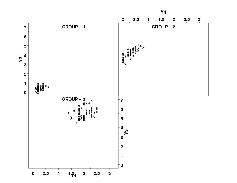
skip 25 read iris.dat y1 y2 y3 y4 group . multiplot corner coordinates 10 5 90 90 tic offset units screen xtic offset 5 10 ytic offset 5 5 char x line blank . condition plot y3 y4 group
Date created: 06/05/2001 |
Last updated: 12/04/2023 Please email comments on this WWW page to [email protected]. | ||||||||||